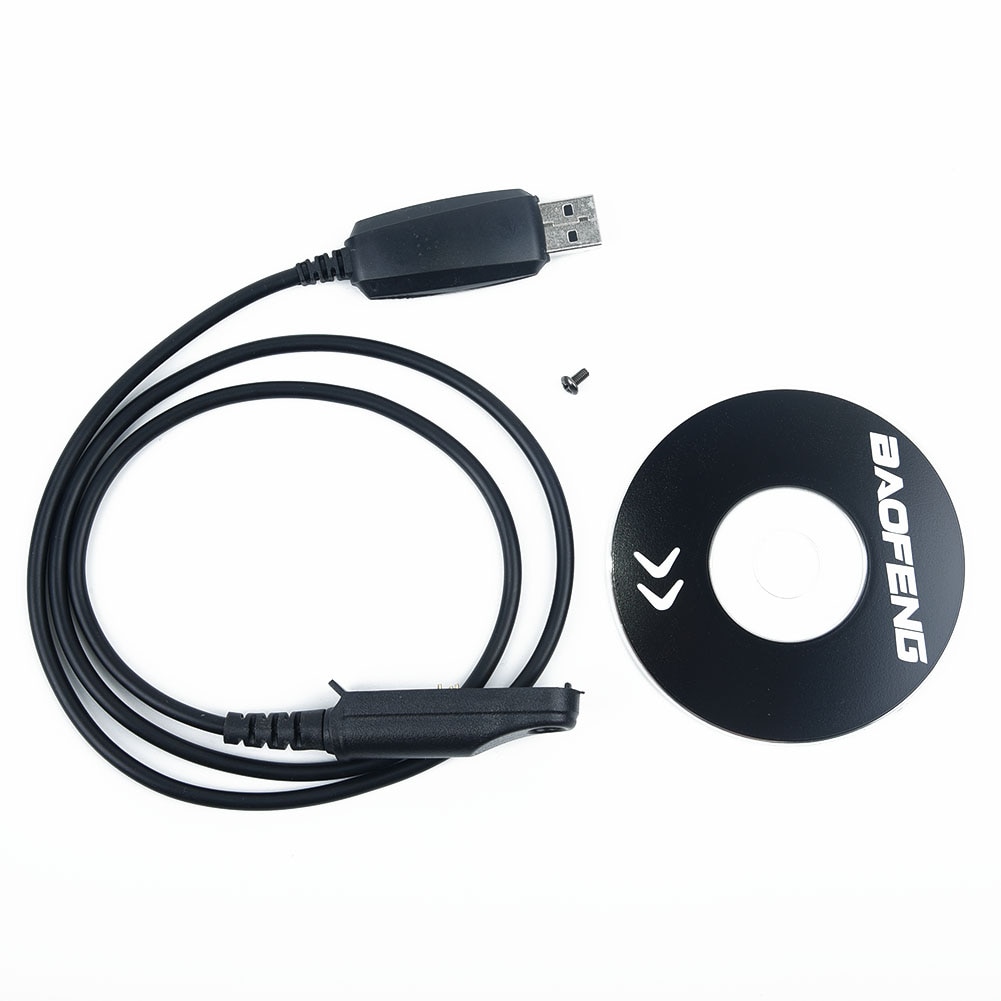

Uv9R 15W Baofeng Programming How To Program A
It does not store any personal data. Unfortunately for unsuspecting owners, Prolific responded to the flood of cloned chips by changing their driver to only work with genuine Prolific chips, so if you have the latest driver, a programming cable based on a cloned chip won't work. This Baofeng UV9RPlus Dual Band Walkie Talkie is a little different to my other Baofeng UV-5R III walkie talkie.My Baofeng UV9R Plus Walkie Talkie YouTube Video above.Fast forward to 5:33 to see how to program a frequency and channel into the Baofeng UV9R Plus.Fast forward to 8:00 to hear actual walkie talkie in action while I take a stroll along the shore of a lake.Setting up this Baofeng UV9R Plus Walkie Talkie, is quite different compared to the Baofeng UV-5R III that I reviewed earlier.But you will get used to it very fast, and once you do, you'll love it.This radio is crystal clear, with long range and good battery life, it is even waterproof to a meter or so.I use this as my goto walkie talkie, and its great for camping and caravanning.A few of the Baofeng UV9R Plus Transceiver features below. You can also buy the programming cable and software package sold by RT Systems, which also have the reputation of "just working", but are expensive.If you don't choose the RT Systems route, then you'll need programming software. Baofeng has free software for their radios.
The cookie is used to store the user consent for the cookies in the category "Analytics".The cookie is set by GDPR cookie consent to record the user consent for the cookies in the category "Functional".This cookie is set by GDPR Cookie Consent plugin. The cookie is used to store the user consent for the cookies in the category "Other.This cookie is set by GDPR Cookie Consent plugin. The cookies is used to store the user consent for the cookies in the category "Necessary".This cookie is set by GDPR Cookie Consent plugin.
Both jumper cables should be reading around 3.8v.*make sure you use the screw to fasten the connector to the radio. Using a multi-meter (set to read voltage), connect the GND jumper cable to the negative multi-meter probe, and the positive to either the RXD or TXD jumper cables (you will need to test both). It is also recommended you tin the pins on the jumper cables with solder before soldering to circuit board.Once complete, run your jumper cables through your connector housing and clip the connector shut (you may need to modify the housing if you have any clearance issues, just make sure the connector will still fit properly to your UV-9R).Yours may be different so make sure you take note of what you used and adjust this guide accordingly.2. Personally, I like to use black for the ground (GND) pin where possible. Now you should have a circuit board with 3 pins attached, these three pins should be RXD, TXD, GND.Using 3 of your 4 jumper cables you will need to solder them to the pins, make sure you take note of what color jumper cables you used.


 0 kommentar(er)
